 |
"Members of the Royal Institution and other visitors to a laboratory in
an upper room in Frith-street, Soho, on Tuesday saw a demonstration of
apparatus invented by Mr. J. L. Baird, who claims to have solved the
problem of television." From an article on page 9 in the London
Times for Thursday, January 28, 1926.
"It [Italy] possesses a Government under the commanding leadership of
Signor Mussolini which does not shrink from the logical consequences of
economic facts and which has the courage to impose the financial remedies
required to secure and to stabilise the national recovery." From a speech
by Winston Churchill, Chancellor of the Exchequer, announcing that Britain
was granting Italy a loan of 80 million £ ($400 million) at 5% interest
per annum and maturing in 1987. Reported on page 1 of the same issue of
the London Times. |
IC graphic
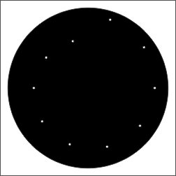
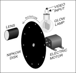
Fig. 1 A Nipkow disk.
|
Nipkow Disk Television
August 16, 2008
 he picture on the right shows what a Nipkow disk
looks like. It's a thin, typically metallic, disk, perhaps .02 inches thick, and
some 30 or more inches in diameter. To reduce its mass, it might have spokes. It has a series of small holes, in this case
10, but more usually from 30 to 240, arranged on a spiral. The angular spacing
of all the holes is the same.
he picture on the right shows what a Nipkow disk
looks like. It's a thin, typically metallic, disk, perhaps .02 inches thick, and
some 30 or more inches in diameter. To reduce its mass, it might have spokes. It has a series of small holes, in this case
10, but more usually from 30 to 240, arranged on a spiral. The angular spacing
of all the holes is the same.
The Nipkow disk takes its name from its inventor, Paul Nipkow, who invented
it in 1884 as a means of sending pictures over telegraph wires. Nipkow never
created a working model of his invention.
To see how this extremely simple device can be used to create television
images we need to break any television system into its elementary components.
These are tabulated in the left column of the following table. The right hand
column tabulates the devices used to implement these functions in television
systems of the mid 1920's.
|
| Functions of Any Television System
| Implementing Device (1920's)
|
| 1
| Imaging the three dimensional scene onto a flat plane.
| Camera lens
|
| 2
| Sequentially sampling the brightness of the image.
| Nipkow disk
|
| 3
| Converting the brightness samples to electrical currents.
| Photocell
|
| 4
| Transmitting the electrical currents to a receiver.
| Radio wave
|
| 5
| Converting the electrical currents to brightness.
| Glow lamp
|
| 6
| Spatially distributing the brightness samples in the same way they
were created.
| Nipkow disk |
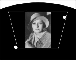
Fig. 2 Scene image projected onto the Nipkow
disk. |

Fig. 3 Scan pattern of a Nipkow disk in slow
motion. |
If we place a lens between the subject and the Nipkow disk, we can image the
subject onto an area on the surface of the disk near its top as shown in figure 2. If we
rotate the disk counterclockwise, the holes in the disk will scan horizontally across the
image in concentric circular arcs moving progressively from the top to the
bottom of the image as shown in figure 3. In an alternate version, the image can be placed
on the left side of the disk. In this case the scan lines are vertical and the frame is
scanned from left to right.
Item 3 in the table is a device for converting the varying elementary
brightness of the scanned image into a correspondingly varying electrical
current. In the early days of television, the preferred device for this function
was a selenium photocell.
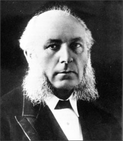
The photoconductive property of selenium was discovered by Willoughby Smith
(Fig. 4). Smith's profession was the design of undersea telegraph cables. He
reported his discovery that the electrical conductivity of selenium was
dependent on the intensity of light impinging on it to the British Society of
Telegraphic Engineers in a letter dated February 4,1873. By the 1920's selenium
photocells were readily available.
From Television, by R.W. Burns.
Fig. 4 Willoughby Smith, 1828 -
1891.
|
Ironical Chronicle graphic.
Fig. 5 Arrangement of elements for televising an
image. |
Ironical Chronicle graphic.
Fig. 6 Arrangement of elements for receiving an
image. |
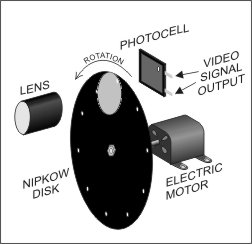
Fig. 5 shows the arrangement of the elements of a system for televising an
image as implemented in the mid 1920's. The scene to be televised is imaged onto
a portion of the disk by the lens. This image is scanned by the holes in the
Nipkow disk. By connecting a battery in series with the photocell, the
variations in the brightness of the light falling on the photocell are converted
to an electrical current varying in proportion to the brightness of each spot on
the image as it is scanned by the disk.
At the time that Nipkow invented his disk, the only known means for carrying
these current variations to a remote receiver were electrical wires. However, on
November 11, 1886, Heinrich Hertz had experimentally verified James Clerk
Maxwell's prediction of the possibility of radio waves. Hertz's laboratory
experiments were reduced to practical radio communication by Guglielmo Marconi
in 1901. Thus, by the mid 1920's, radio waves as a means for carrying the video
signal to a remote receiver were available.
Fig. 6 shows the system for reassembling the image at the receiver. The
receiving system is identical to that of the originating system except for the
element which converts the video currents back to brightness variations and the
fact that the reconstructed image is now viewed through the lens.
From Television, by R.W. Burns.
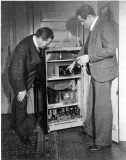
Early GE TV receiver. The glow lamp can be seen in the
center of the top shelf of the cabinet. The engineer is pointing to the
motor which rotates the disk.
|
The glow lamp in Fig. 6 is a kind of lamp whose brightness can respond
instantly to changes in current. In the light sources used at the time, it
consisted of two electrodes in a glass envelope containing an ionizable gas. The
amplified signal from a radio receiver tuned to the television transmitter's
frequency is applied to the terminals of the glow lamp. If the Nipkow disk at
the receiving end is synchronized with the one at the transmitting end and if
both disks are spun fast enough, the viewer's persistence of vision will create
the illusion of a complete image, including its movement.
In motion picture projection, the standard frame rate is 24 frames per
second. In the Nipkow disk-based system, a frame corresponds to one rotation of
the disk. Thus, to duplicate the motion picture standard frame rate, the disk
would have to rotate at 1440 revolutions per minute.
The early Nipkow television systems raised issues in communication theory
which had not previously been considered. The most fundamental was probably the
relationship between the resolution of the image and the bandwidth of the radio
signal which carried the video information. High resolution meant a large
bandwidth and a large number of scan lines. In the Nipkow system, the number of
scan lines is equal to the number of holes in the disk.
In the earliest experiments, ten hole disks were used. In its highest form of
development, reached in the mid 1930's, disks with 240 holes were used.
Thereafter, all-electronic systems, which had been under development since the
late 1920's, made the mechanical Nipkow disk scanner obsolete. The standard
television signal broadcast in the US since the 1950's has been a 525 line
system operating at 30 frames per second.
The first public demonstration of a television system was given by John L.
Baird in London on Tuesday, January 26, 1926. A report of it appeared on page 9 of the London Times
two days later.
It used a vertical scanning Nipkow disk.
The following two links present a human interest side of this story of the
early days of television.
- LINK A film of a 1930 broadcast taken directly
from John Baird's Nipkow disk scanner. It is a performance of Luigi
Pirandello's 1923 play, The Man With A Flower In His Mouth.
- LINK A biographical sketch of Imogen
Orkutt. Imogen was a model for early German television tests.
OTTO